Unlock the Secrets of Raspberry Pi 4 Pinout Now!
Explore the Raspberry Pi 4 Pinout and unleash its potential!
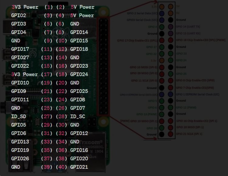
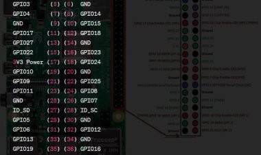
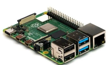
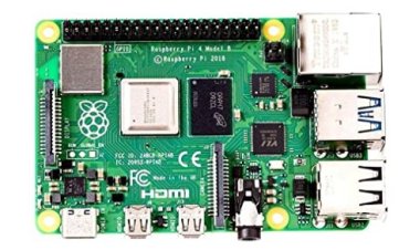
The Raspberry Pi 4 Pinout Model B has a 40-pin GPIO header, which is utilized for universally useful information/yield (GPIO) and to communicate with different outer gadgets and parts. Here is a rundown of the GPIO pins on the Raspberry Pi 4
- 3.3V Power
- 5V Power
- SDA1 (I2C)
- 5V Power
- SCL1 (I2C)
- Ground
- GPIO 7
- TXD (UART)
- Ground
- RXD (UART)
- GPIO 0
- GPIO 1
- GPIO 2
- Ground
- GPIO 3
- GPIO 4
- 3.3V Power
- GPIO 5
- MOSI (SPI)
- Ground
- MISO (SPI)
- GPIO 6
- SCLK (SPI)
- CE0 (SPI)
- Ground
- CE1 (SPI)
- SDA0 (I2C)
- SCL0 (I2C)
- GPIO 21
- Ground
- GPIO 22
- GPIO 26
- GPIO 23
- Ground
- GPIO 24
- GPIO 27
- GPIO 25
- GPIO 28
- Ground
- GPIO 29
These pins can be arranged in various modes (GPIO, UART, I2C, SPI, and so forth) to cooperate with different electronic parts and gadgets. Kindly guarantee you utilize the fitting mode and play it safe while working with GPIO pins to forestall any harm to your Raspberry Pi or associated parts.
3.3V Power
central issues about the 3.3V power on the Raspberry Pi:
- Voltage Guideline: A voltage controller circuit on the Raspberry Pi changes over the information voltage (normally 5V) to a consistent 3.3 volts.
- Utilization: The 3.3V power is utilized for low-voltage parts like ICs, sensors, and computerized gadgets on the Pi.
- GPIO Rationale Levels: Numerous GPIO pins work at 3.3V rationale levels, essential for interacting with outer parts.
- Similarity: The 3.3V stock guarantees similarity with sensors and gadgets intended for 3.3V rationale.
- Alert: Be cautious while working with 3.3V power and different pins to stay away from harm. Continuously check associations and power necessities.
5V Power
central issues about the 5V power on the Raspberry Pi:
- Voltage Guideline: The Raspberry Pi has a voltage controller that switches the information voltage over completely to a consistent 5 volts.
- Utilization: The 5V power is utilized for different parts like USB ports, HDMI result, and a few sensors.
- USB Power: It controls the Raspberry Pi's USB ports for associating peripherals straightforwardly to the board.
- GPIO Header: Not all GPIO pins can deal with 5V; be careful when connecting with outer parts that work at 5V rationale.
- Power Contemplations: Utilize a dependable power supply that can give sufficient current to the board and associated peripherals.
- Alert: Exercise mindfulness to try not to harm the Raspberry Pi or associated parts; check associations and power necessities.
SDA1 (I2C)
SDA1 represents Sequential Information Line 1 and is important for the Between Incorporated Circuit (I2C) correspondence convention. It is one of the two fundamental lines utilized in I2C correspondence, the other being SCL (Sequential Clock Line). The Raspberry Pi has different I2C interfaces, and SDA1 relates to the principal I2C interface accessible on the board.
I2C Correspondence Convention: I2C is a generally involved sequential convention for consistent correspondence between numerous gadgets on similar transport, ideal for sensors, show modules, and coordinated circuits.
SDA (Sequential Information Line): The bi-directional SDA line sends and gets information between the expert (microcontroller or Raspberry Pi) and slave gadgets on the I2C transport.
I2C Transport: Supports various gadgets with special locations. The expert starts correspondence by tending to explicit slaves through SDA and SCL lines.
Clarification of the GPIO pins
- GPIO 0 (BCM 17): This pin is a broadly useful information/yield pin. It tends to be designed as an info or result pin contingent upon the application. It compares to BCM (Broadcom) pin 17.
- GPIO 1 (BCM 18): Like GPIO 0, this is another universally useful information/yield pin. It compares to BCM pin 18.
- GPIO 2 (BCM 27): Another broadly useful info/yield pin. It compares to BCM pin 27.
- GPIO 3 (BCM 22): This pin is a universally useful information/yield pin. It relates to BCM pin 22.
- GPIO 4 (BCM 23): Like GPIO 3, this is another universally useful information/yield pin. It compares to BCM pin 23.
- GPIO 5 (BCM 24): Another broadly useful information/yield pin. It relates to BCM pin 24.
- GPIO 6 (BCM 25): This pin is a universally useful info/yield pin. It relates to BCM pin 25.
- GPIO 21 (BCM 9): This pin is a broadly useful information/yield pin. It compares to BCM pin 9.
- GPIO 22 (BCM 25): Like GPIO 6, this is another broadly useful information/yield pin. It relates to BCM pin 25.
- GPIO 26 (BCM 7): This pin is a broadly useful information/yield pin. It relates to BCM pin 7.
- GPIO 23 (BCM 11): This pin is a broadly useful information/yield pin. It compares to BCM pin 11.
- GPIO 24 (BCM 8): This pin is a universally useful information/yield pin. It compares to BCM pin 8.
- GPIO 27 (BCM 0): This pin is a broadly useful info/yield pin. It relates to BCM pin 0.
- GPIO 28 (BCM 1): This pin is a broadly useful info/yield pin. It relates to BCM pin 1.
Ground
TXD and RXD, often shortened to Tx and Rx, are like the chatty messengers of microcontrollers, including the Raspberry Pi. They stand for Transmit and Receive, and they're part of a communication method called UART, which is short for Universal Asynchronous Receiver/Transmitter. This fancy term just means it's a widely recognized way for gadgets to exchange data back and forth. So, imagine Tx as the microcontroller's way of saying, "Hey, here's some data!" and Rx as its way of listening for replies like, "Got it, thanks!" It's the language of digital conversations between devices.
TXD (Communicate Information): Results information sequentially to the getting gadget by means of the TXD pin.
RXD (Get Information): Data sources information sequentially from the sending gadget through the RXD pin.
UART Correspondence: UART Communication is a bit quirky but effective, relying on a standard baud rate to determine how fast data travels. Each data package has its own little 'hello' and 'goodbye' with start and stop bits framing them up neatly. When it comes to Serial Communication, it's like playing catch with data: TXD throws it out there, while RXD catches it on the other end. It's this back-and-forth dance that keeps gadgets chatting seamlessly.
Sequential Correspondence: Uses TXD for sending and RXD for getting information.
Equipment and Programming UART: Microcontrollers might have both equipment and programming UART abilities. Equipment UART is more proficient and less computer processor serious.
Utilizing UART on Raspberry Pi: GPIO pins 14 (TXD) and 15 (RXD) compare to equipment UART.
Designing UART: Empower UART in settings, handicap its utilization as a control center if necessary, and program in Python, C, and so on, for information transmission and gathering.
MOSI (SPI), MISO (SPI), SCLK (SPI), CE0 (SPI)
SPI, which stands for Serial Peripheral Interface, is basically this super common way for devices to chat with each other in embedded systems. It's like their own secret language! What's cool about it is that it allows for full-duplex communication, meaning devices can talk and listen at the same time. So, imagine them having a seamless conversation without interrupting each other. It connects microcontrollers and devices using multiple signal lines:
MOSI (Master Out Slave In): Expert sends information to the slave.
MISO (Master In Slave Out): Slave sends information back to the expert.
SCLK (Serial Clock): Expert's clock signal synchronizes information move.
CE0 (Chip Enable 0): Expert chooses a particular slave gadget for correspondence.
SPI interacts with sensors, memory chips, converters, and so forth, offering higher information rates and direct equipment level correspondence.
On Raspberry Pi, SPI is accessible through GPIO pins:
MOSI: GPIO 10 (Pin 19) MISO: GPIO 9 (Pin 21) SCLK: GPIO 11 (Pin 23) CE0: GPIO 8 (Pin 24) Enable SPI in settings, load kernel modules, and use Python, C, etc., to interact with SPI devices.
For smooth communication between devices, it's crucial to get the clock frequency and data format just right. Think of it like tuning two instruments to play the same melody.
Firstly, nail down the clock frequency. This determines how fast data moves between devices. It's like setting the tempo for a song—both sides need to keep in sync. Make sure both devices agree on the frequency so they can understand each other clearly.
Secondly, get the data format down pat. This includes details like how many bits make up each piece of data, whether there's any parity involved, and how many bits are used to signify the end of a message. It's like speaking the same language—both devices need to follow the same rules to understand each other correctly.
By fine-tuning these settings to match the needs of your devices and communication protocol, you pave the way for successful and reliable data exchange.
conclusion
-
Power: The 3.3V and 5V power pins furnish capacity to associated parts with their particular voltages.
-
Ground (GND): These pins serve the humble yet vital purpose of providing ground connections. They're like the sturdy foundation of a building, ensuring a stable and reliable electrical pathway for the devices they connect.
-
GPIO (General Purpose Input/Output): These pins are programmable and can be utilized for various purposes, like perusing sensor information or controlling actuators.
-
ID_SD and ID_SC: These pins are utilized for the I2C connection point to speak with different gadgets.
Remember that various activities and applications might require different pin setups, and not all pins are appropriate for universally useful use. A few pins have explicit capabilities, like UART, I2C, SPI, PWM, and so forth.
If you want the latest and most detailed scoop on the Raspberry Pi 4 Model B pinout, your best bet is to head straight to the official Raspberry Pi documentation or the manufacturer's website. They've got all the juicy details and updates you need to know about those pins!